I’ve been spending the last few weeks working with a system based on UE5’s Gameplay Ability System. In order to learn the general basics of the system I learned quickly that the best resource at the moment for a working example is a great tutorial by Leonard Parisi that exists on his Youtube channel and GitHub.
I’ve been working in a sample project for sandboxing and have found that this system allows for very quick prototyping. While it has a steep learning curve, once the basics are understood it makes it easy to create a playable experience.
I’ll be adding more details and examples from my sample project in the future, but I wanted to make note of my current references before I forget.
This section is about Arrays, and more specification on other useful nodes.
Arrays
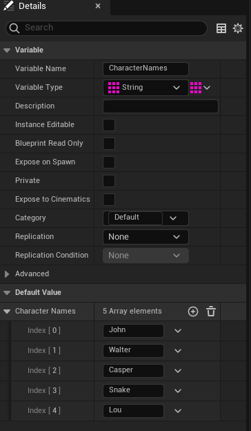
Simply put, arrays are a collection of elements.
In the above example, the array here is a variable of strings which are defined in the Array elements list.
To create an example array, do the following steps:
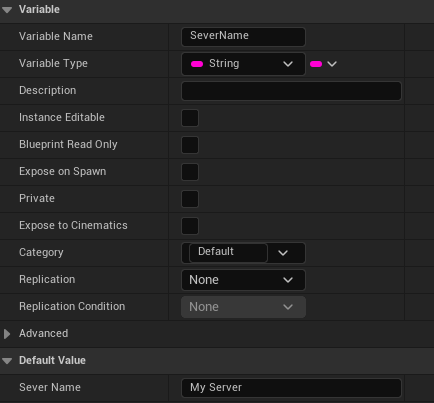
Create a variable and name it. In this case, we’re using a string variable.
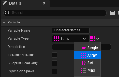
After creating the variable, go to the Details view of your new variable and under “Variable Type”. There is a button to the right of that dropdown box. Select it, and select “Array”.
3. After compiling, you can begin populating your array with elements in the “Default Value” section.
Items of note:
The initial first “value” in an array lists with “0”.
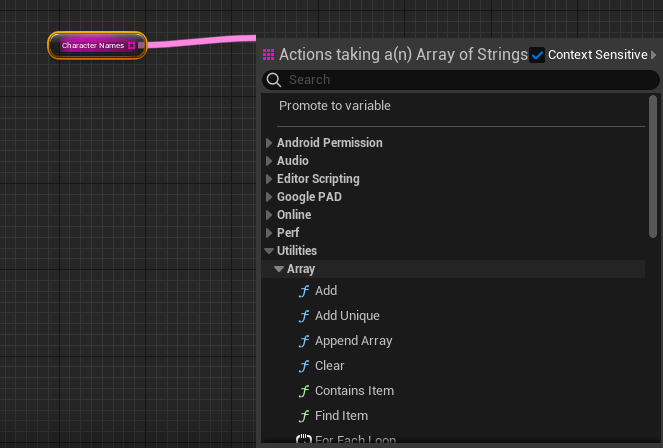
You can get contextual list of “Array Function” nodes by dragging off the Array node > Utilities > Array
More Blueprint Nodes (Flow Control)
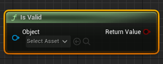
Is Valid Node
Is valid node is useful for checking the state of an object in the level. A good example of using this node is to setup a validation check on if the player has spawned into the level.
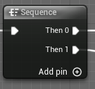
Sequence Node
A sequence node executes graph nodes in sequential order. A sequence node is a useful way to organize and keep a graph compact.
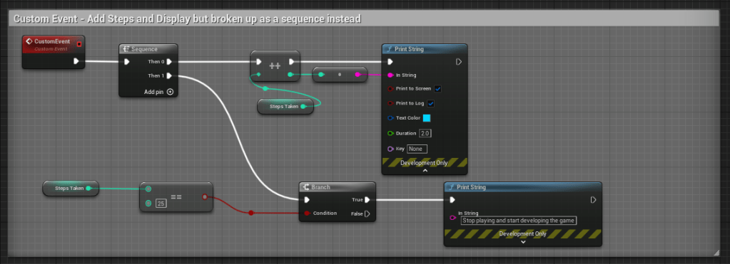
Below are two example ways of setting up a custom event graph, the first does not use a sequence node, but the second example does. Both graphs do the exact same functionality.
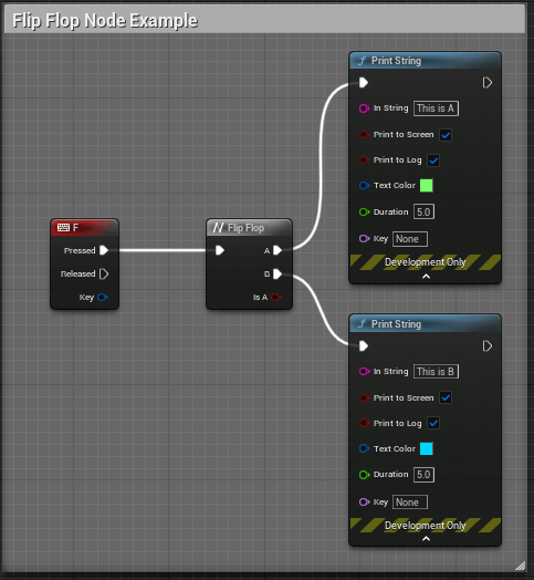
Flip Flop Node
A Flip Flop node switches from A to B on a defined event. Below is an example of a Flip Flop node in use. When the user presses the “F” key input, the functionality will alternate between what is defined in “A” and “B”.
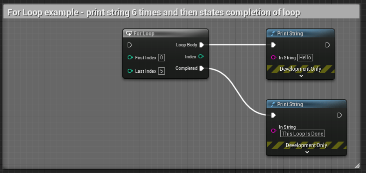
For Loop (Flow Conrol) Node
Loops are used to repeat a defined graph.
The indexes within the node can be variables connected to the node or defined as a specific amount.
Below is an example of a simple “For Loop” that will print string a message on screen 6 times and then print a second message on completion of the loop.
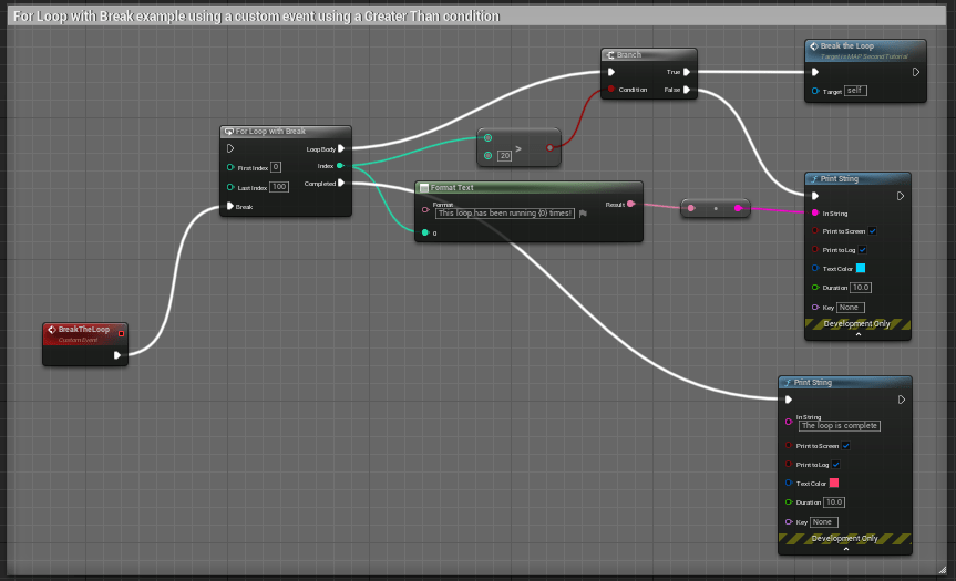
For Loop With Break Node
This node is the same as the above node, but with an additional execution pin, “Break”.
Break can be used to set a custom event* or some other function to occur when a condition is met, and it will “break” the loop.
*Remember that the custom event will need to be called within the loop body, otherwise it will not play.
The above example has some logic to “Break” the loop and call an event when when the loop index is greater than 20.
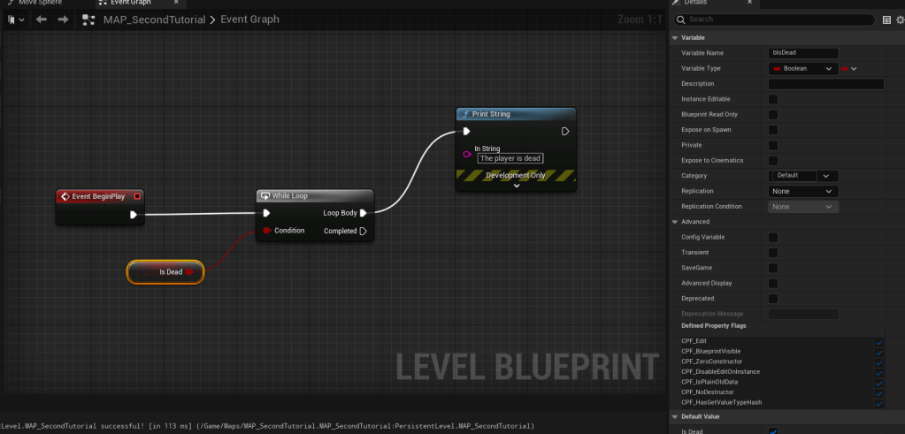
While Loop
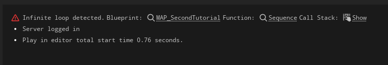
This is a potentially expensive node and should also be used sparingly. For example, I’ve set up a situation where an infinite loop can occur that causes an error.
In the above example, the logic is set to check to see if “IsDead” is occurring. Since there is no defined logic that changes the “IsDead” state the check on loop is infinite and displays the following error when pressing “Play”.
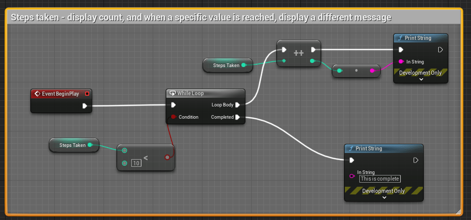
A better example of using “While Loop” is setup here:
In the above example, the condition is looking for an integer value “Less than” 10. When in that threshold, the loop body is incrementing the steps by 1 and displaying the number of steps taken. When the condition is met (10 steps) a different message is displayed on screen.
Do Once & Do N Nodes
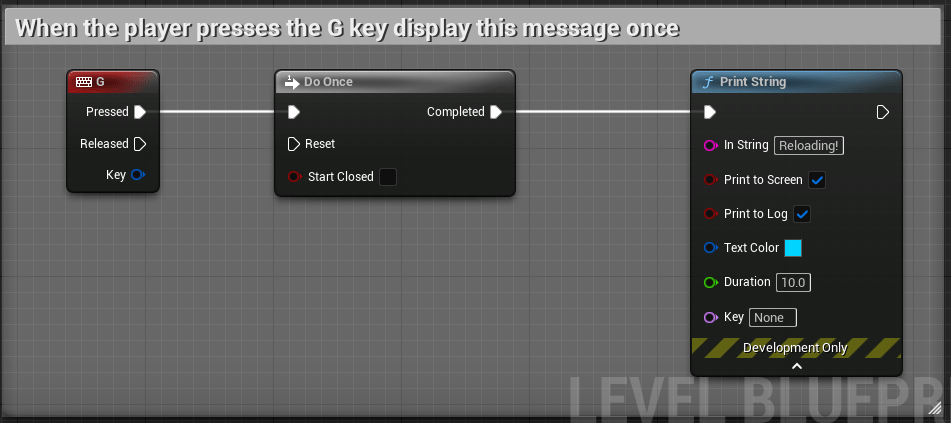
The Do Once node will only do a specified node sequence that is set after this node to occur once, unless another set of logic is defined on “Reset” of the node.
In the above example, when the player presses the “G” key, display this message once.
A better example using a custom event with a reset condition can be seen below.
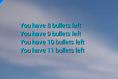
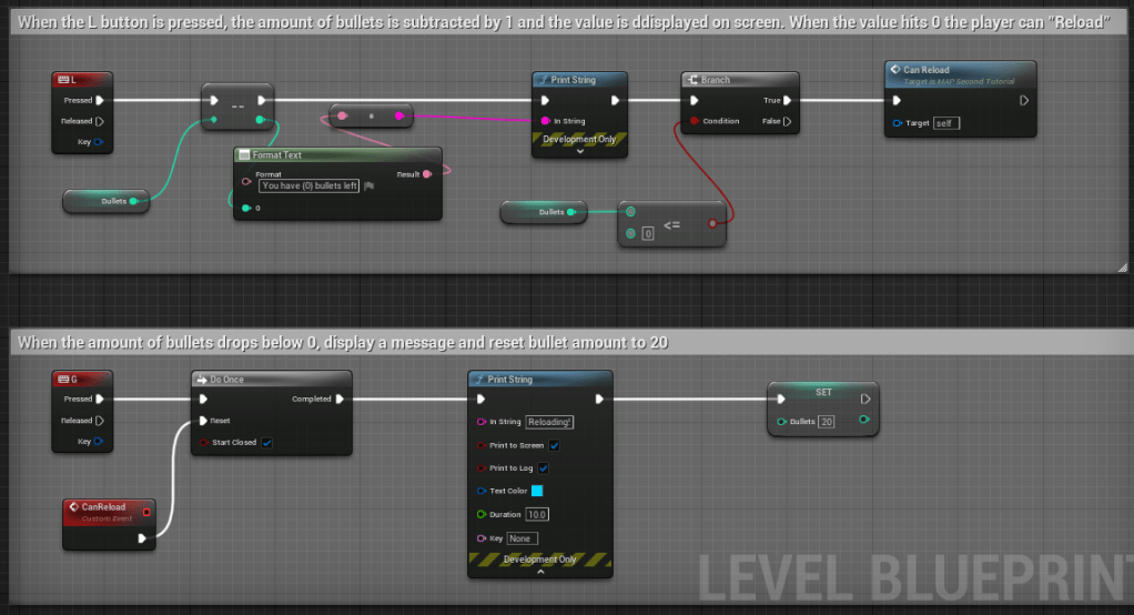
In the above logic, we have defined the amount of bullets to start at “20”. As the player presses “L” a deduction from the starting value of bullets occurs and displays a message. When the player reaches “O” or below bullets, the Branch then initiates the Custom Event, “Can Reload” to become available. The player then presses “G”, which displays a “Reloading!” message and sets the amount of bullets back to 20.
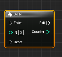
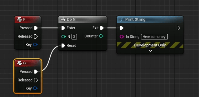
Do N Node
The Do N node can be used to define a sequence to occur a set number of times, by either defining a value in “N” or by using a variable to “count”.
In the above example, after the player has pressed “F” 3 times, no longer display the “Here is money!” message, and then allow the “G” key to reset the condition.
Gate & Multi Gate Nodes
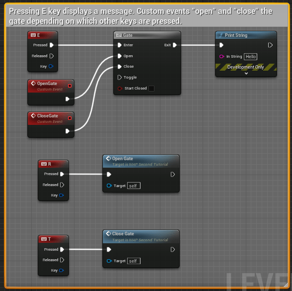
The “Gate” node is used to create a graph sequence that “opens” and “closes” a gate based on the logic defined with execution pins connected to this specific node.
Below is a simple example of “Gating” logic using custom nodes.
By default, the gate is set to “Open” because the “Start Closed” checkbox is unchecked. In this series of logic, pressing “E” will display a message on screen. If the player presses the “T” key, the gate then becomes closed (meaning, the message will not appear on a keyboard press), but pressing “R” will “open” the gate once again.
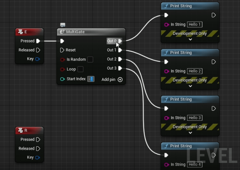
MultiGate Node
The MultiGate Node uses the same principles as the “Gate” node, but has a few more items that can be adjusted, including multiple “Out” execution pins.
In the example above, when the player presses “E”, the MultiGate node runs through each Out sequence as the player interacts with the defined key.
It should be noted that the “Start Index” is defaulted to occur with “Out 0”, but the value can be set within this node.
The gate will also stop after the final execution pin has completed unless the “Loop” option within the node is checked.
The “Is Random” checkbox can also be used to “randomize” the outcome.
More details and breakdown notes for this post, including information on Event nodes, Custom Events, Functions, and Macros.
Blueprint Nodes, Part 2
Event Nodes
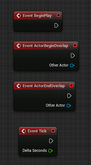
Event nodes are red in color and typically are the starting node in a graph sequence.
An important note! The most expensive and rarely used Event node is the “Event Tick” because of how frequently it “ticks”, which is 60 times per second!
Common Event Node Types
The following are some of the more common event node types frequently used when creating Blueprints. These
Event BeginPlay: Executes associated graph nodes on “Play” of level.
Event ActorBeginOverlap: Executes the graph associated when an entity begins an overlap with a defined “actor”. A common actor used is a “trigger volume”.
Event ActorEndOverlap: Executes the graph associated when an entity exits an overlap with a defined “actor”. A common actor used is a “trigger volume”.
Custom Nodes
Custom Events
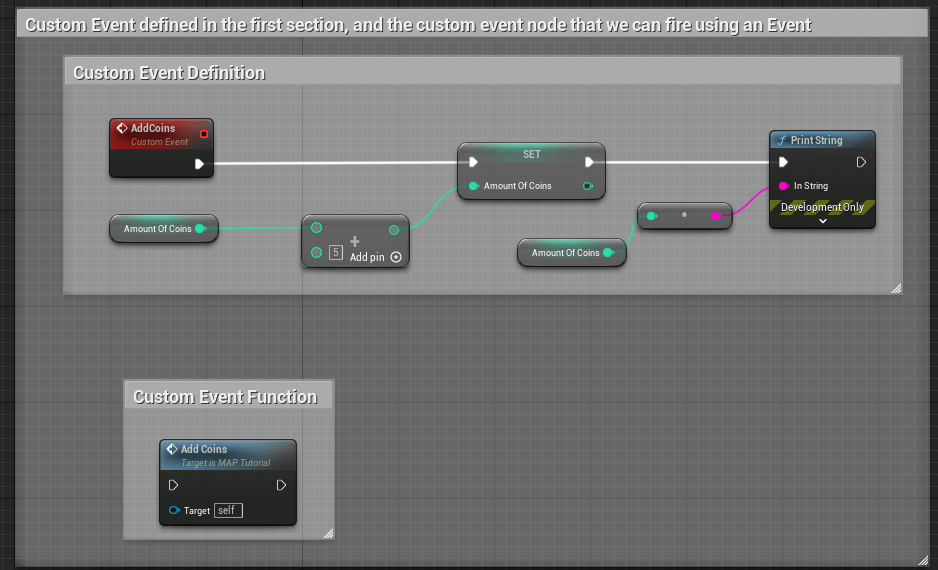
Custom events are event nodes that are specifically defined by a user.
Think of custom events as a larger container of nodes that you will prefer to organize and define once so you can easily reference them using one node instead of duplicating graphs repeatedly.
In the above example, a custom event here is called “AddCoins”. When the event is called, the amount of coins is increased by a value of “5” and the updated amount is displayed using a Print String node.
Special notes on custom events:
Events cannot have return values or local variables like functions, but the key difference between Custom Events and Functions is that Custom Events are asynchronous by nature.
Defining “Asynchronous by nature”: You can manipulate time inside custom events (adding delays or timelines). Also, you can replicate them over network (which means they are multiplayer friendly!).
Functions
Functions are node graphs belonging to a particular Blueprint that can be executed, or called from another graph within the same Blueprint. Functions have a single entry point designated by a node with the name of the Function containing a single execution output pin (in the above example, notice there is only one entry and exit pin on the blue node below the larger graph).
Special notes on custom events:
You can create a new function by selecting all of the nodes that pertain to a specific graph that you’d like to group as a function, right click in the BP editor, and select “Create Function”.
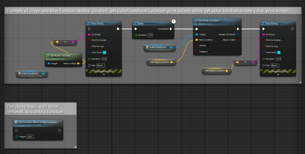
Timed attributes, such as delay, cannot be used in a function (as noted above in the comment of the function example).
After creating a function, if you double-click on the node it will display all node logic in a separate graph tab for reference and adjustments.
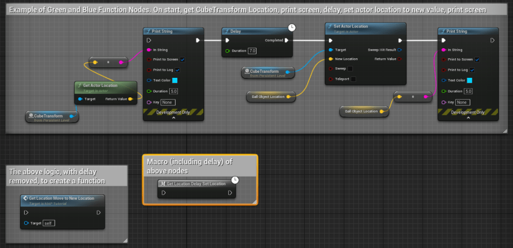
Green vs. Blue Function Nodes
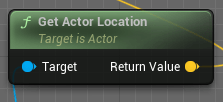
For simplicity sake, we can define Green Function Nodes as Pure Function nodes, which has no execution pins. Pure functions are wired to Data Pins and are automatically executed by the compiler when the data relying on them is required. This means that a Pure Function will be called one time for each node it is connected to.
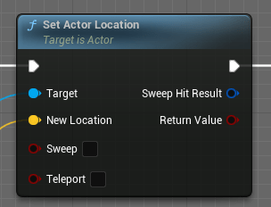
Another way to define the difference between Green and Blue function nodes is that Green nodes “Get” info, while Blue nodes can “Set” info.
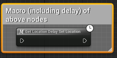
Macros
Macros are very similar in functionality to Functions, but they can contain delayed or timed function nodes. In the example above, the graph is fully encapsulated in the macro, and has a designated icon on it to indicate a timed event is part of the graph set.
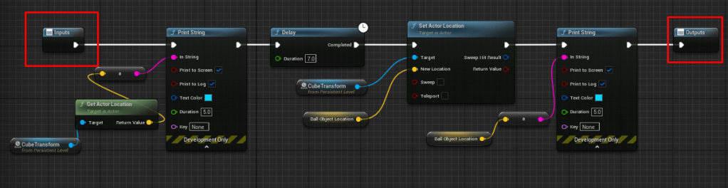
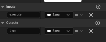
Defining Execution Pins for Macros
In the above example, this macro has an input and output execution pin defined. You’ll need to make sure in your graph that you define any variable needed to make an execution pin available.
To add an input and output pin, select the end node of your graph and look in the details panel of the BP editor. Locate the Inputs and Outputs values and add new.
Working through the following Udemy course as a way to get more familiar and comfortable with visual scripting.
I’m going to break down a few aspects of the learnings I’m going through for future reference for myself any anyone else who may need a quick primer on the fundamentals of Blueprints. These notes are more like quick bullet points with reference images attached to each to show some of the logic used to understand each category listed below.
General Notes
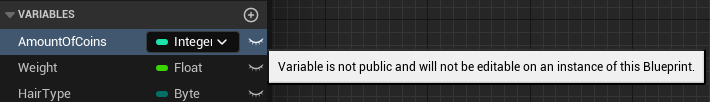
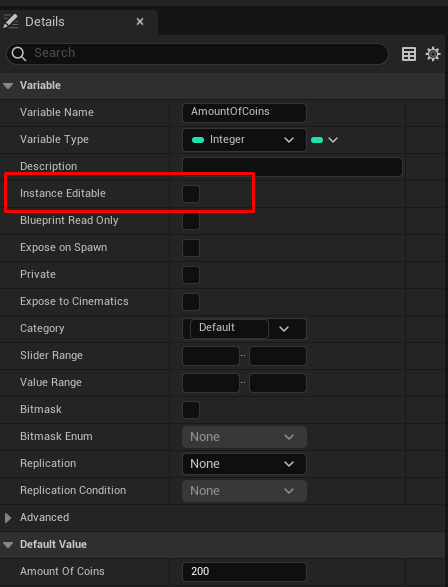
The order of operations for a blueprint follows conventional flow: Nodes flow from left to right and fire within the order organized. A variable can also be set to be manipulated based on its instance in a level by setting the “Eye” icon next to its variable name to “open”.
This change can also be set within the details panel of the variable here:
The difference between “Get” and “Set” when adding variables to blueprints.
When “Getting” a variable, you are just querying to get the defined value of the variable. When “Setting” a variable, you are altering the variable dynamically when called.
A Breakdown of Variables
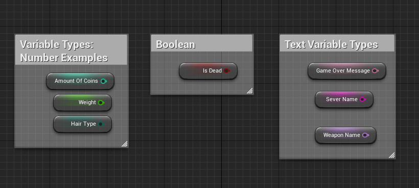
Most Common Variables
Boolean – A variable value that is either true or false. Integer – Numeric variables that are whole numbers. Float – Numeric variables that can contain decimals. Byte – Values that are also whole numbers but the max value that can be defined is 255. Bytes also use less memory due in part to its value constraints.
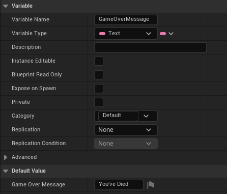
Text Variables:
Text – An input variable of specific text directly defined in the variable. Out of all the text-specific variables, this uses the most memory and can be localized.
String – Another text input variable. This specific piece of text cannot be localized and uses a medium amount of memory.
Name – Text input variable that uses the least amount of memory, cannot be localized and cannot have “append” functionality.
Manipulation Variables:
The following variables can manipulate a game object’s positioning within the world.
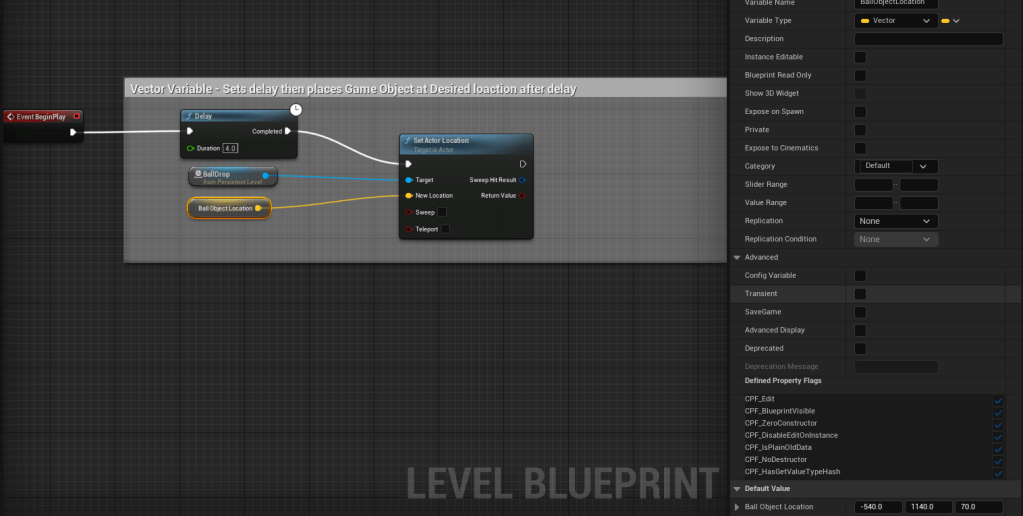
Vector – Contains 3 numeric input values typically associated with location in the defined space. Can alter an object’s location when variable is called.
In the above example, the following logic is occurring. On Event BeginPlay (start of play) Delay this action by 4 seconds, then set target (in this case, it’s a level object called “BallDrop”) to change location to the variable input.
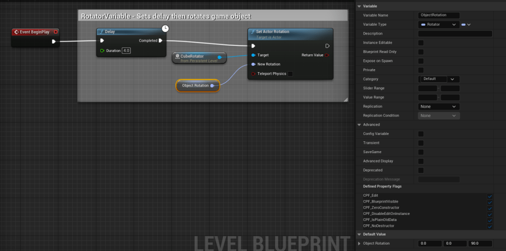
Rotator – Used to change a rotation of an item.
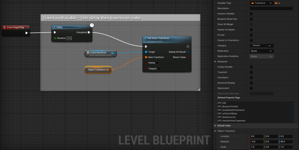
Transform – Used to change the full transform of an item, such as scale, rotation, and location.
Operators and Conditionals:
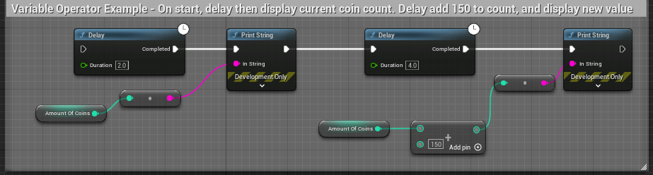
Variable operators – math elements, like addition, subtraction, multiply, divide that can be used to adjust a variable’s value.
In the above example, this series of nodes are set to do the following in order: 1. Delay by 2 seconds 2. Check and display amount of coins 3. Delay after display by 4 seconds 4. Add 150 to the current amount of coins 5. Display new coin value
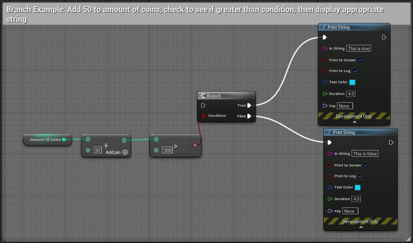
Branches – “IF statement” Node. Checks an input value and determines if it is “true” or “false” and follows the proper flow outcome of definition. Branch condition values need to be defined as a bool to define a “true” or “false” outcome.
Branches can use conditionals to evaluate data criteria, such as <, >, <=, >=, != (not equal), == (equal).
Hello again, it’s been a while! I’ve had a few job changes over the last few years, and each role has required me to work more in documentation than in a scripting capacity. I must say, I was worried about getting rusty, and even though a lot of the dust is knocked off, I’m still very much an Unreal Engine noob.
The interface, file structure, and content-building tools are all pretty standard and very easy to get familiar with, but Blueprints continue to be a challenge. Because of this, I wanted to list out a few resources that helped me at least get a basic understanding of Blueprints. They’re great reference points that I’ll continue to use for a long while.
I’m about 75% of the way through this lesson from Unreal’s learning resource center. I really like all of the available lessons and especially appreciate their Badge system which helps mark a learner’s progress through a fun little achievement system. The overall resources out there for learning and utilizing Unreal is astounding and I appreciate all of that information placed in one unified location with easy search tools.
The next lesson I’m going to jump into is a course on Gamedev.tv that explores Blueprints and provides users with hands on experience creating a prototype simple game. I’m pretty excited about this one and can’t wait to do some more hands-on application with the editor.
An example image of a blueprint from “Exploring Blueprints” lesson
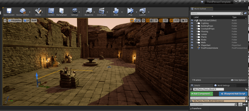
Running through introduction tutorials and built my first level using free assets in the Epic Store. Having all of the items in one spot, including the market place, the Epic Launcher, and the Unreal Engine in one shell is really cool.
I only dabbled in Blueprints creating a prop light, but I think I’m going to really enjoy tooling around with the options. After using Unity for so long, I was worried Unreal would be difficult to learn, but it’s pretty intuitive so far; let’s see how I feel about that after a few more days.
Very much looking forward to creating more actors and using assets to build something playable.
For reference, these are the tutorials I ran through today:
Introducing Unreal Engine – Really great introduction to all of the components that make up the editor.
Your First Hour With Unreal Engine -A very, very quick overview on importing assets, creating your first level, adjusting lighting, and creating a simple Blueprint.